|
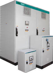
WHAT SIZE PFC PANEL DO I NEED?
|

Rating - 125 kVAr - £4,334.00 incl VAT
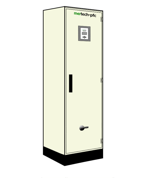
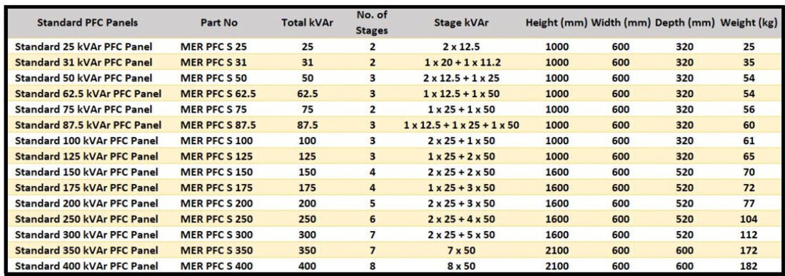
3 Stages - 2 x 50kVAr - 1 x 25 kVAr Automatic Controller Incoming TP Isolator Part No - MER PFC S 125 Dims (mm)- 1000H x 600W x 320D |
Rating - 150 kVAr - £5,134.00 incl VAT
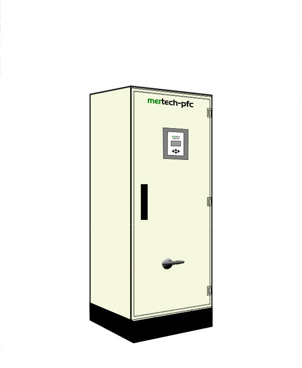
4 Stages - 2 x 50kVAr - 2 x 25 kVAr Automatic Controller Incoming TP Isolator Part No - MER PFC S 150 Dims (mm)- 1600H x 600W x 520D |
Rating - 200 kVAr - £5,908.00 incl VAT
5 Stages - 3 x 50kVAr - 2 x 25 kVAr Automatic Controller Incoming TP Isolator Part No - MER PFC S 200 Dims (mm)- 1600H x 600W x 520D |
Prices are incorrect, please contact the office.
For De-Tuned models please contact us.
If your system or network has harmonic distortions, it is strongly recommended not to do the power factor correction with just the aid of capacitors as they can trigger phenomena of parallel resonance with the network, leading to an amplification of the existing harmonics. Under these circumstances a de-tuned PFC system is required, and it is suggested identifying the resonance frequency of the tuned circuit composed of the power factor correction capacitor and the mainly reactive impedance of the network.
In the light of the above, it is recommended to analyse the network correctly when there are certain kinds of load before choosing the type of power factor correction. We therefore recommended you contact a network specialist that will be able to help and guide you in choosing the appropriate equipment.
In the light of the above, it is recommended to analyse the network correctly when there are certain kinds of load before choosing the type of power factor correction. We therefore recommended you contact a network specialist that will be able to help and guide you in choosing the appropriate equipment.
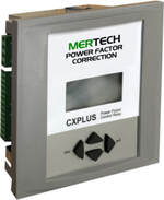
Automatic Controllers
|
|
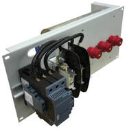
1 x 25kVAr PFC Tray
|
INTRODUCTION
Correct design of electrical installations and service equipments permits reducing waste, but above all a rational use of the electrical energy with ensuing optimisation of the correlated costs.
A fundamental characteristic of minimizing expenses related to the purchase of energy is to reduce losses, starting from generation and on to distribution and use.
Power-factor correction is one of the actions that make it possible to accomplish
substantial energy savings as it:
POWER FACTOR
Much electrical equipment (especially in the industrial field, such as for example motors, transformers, reactors or power converters), in addition to power known as “active power” (P) capable of translating into work of a mechanical nature, heat,light, etc., needs power known as “reactive power” (Q) needed to energize magnetic circuits.
In other words, we can affirm that not all the energy is used to do work, but only the portion relating to active power.
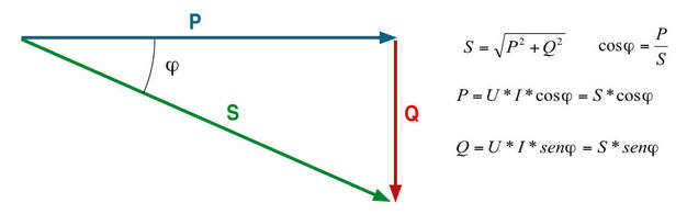
Electric installations must however be designed by taking into consideration power known as “apparent power” (S), given by the product of voltage and current. To clarify matters, it is possible to consider the total current to which the apparent power is associated as the vectorial sum of a resistive component IR (component in phase with the voltage due to the resistive portion of the load), to which the active power P is associated, and the inductive current IL (wattless component due to the inductive portion of the load), to which the reactive power Q is associated.
The apparent power S therefore takes account of both the active power P and the
reactive power Q. Figure A shows the relationship between active, reactive and apparent power by means of the so-called “power triangle.”
The relationship between the active power P and the apparent power S is called the
power factor and is usually indicated as “cos φ”.
Correct design of electrical installations and service equipments permits reducing waste, but above all a rational use of the electrical energy with ensuing optimisation of the correlated costs.
A fundamental characteristic of minimizing expenses related to the purchase of energy is to reduce losses, starting from generation and on to distribution and use.
Power-factor correction is one of the actions that make it possible to accomplish
substantial energy savings as it:
- limits energy losses due to the Joule effect along the cables
- limits drops in voltage along the cables
- reduces plant engineering costs for users, making it possible to utilize conductors with a smaller cross-section
- prevents users from incurring the penalties contained in electrical energy supply contracts.
POWER FACTOR
Much electrical equipment (especially in the industrial field, such as for example motors, transformers, reactors or power converters), in addition to power known as “active power” (P) capable of translating into work of a mechanical nature, heat,light, etc., needs power known as “reactive power” (Q) needed to energize magnetic circuits.
In other words, we can affirm that not all the energy is used to do work, but only the portion relating to active power.
Electric installations must however be designed by taking into consideration power known as “apparent power” (S), given by the product of voltage and current. To clarify matters, it is possible to consider the total current to which the apparent power is associated as the vectorial sum of a resistive component IR (component in phase with the voltage due to the resistive portion of the load), to which the active power P is associated, and the inductive current IL (wattless component due to the inductive portion of the load), to which the reactive power Q is associated.
The apparent power S therefore takes account of both the active power P and the
reactive power Q. Figure A shows the relationship between active, reactive and apparent power by means of the so-called “power triangle.”
The relationship between the active power P and the apparent power S is called the
power factor and is usually indicated as “cos φ”.